1999
Hardware installations on the site
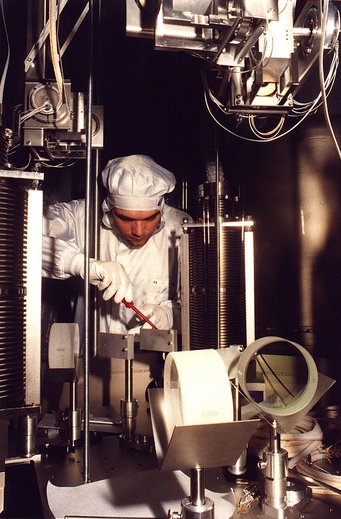
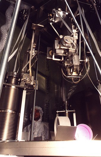
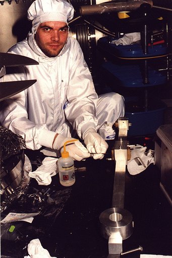
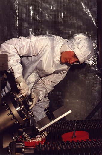
February 1999: Installation of the Modecleaner Tank TCMa
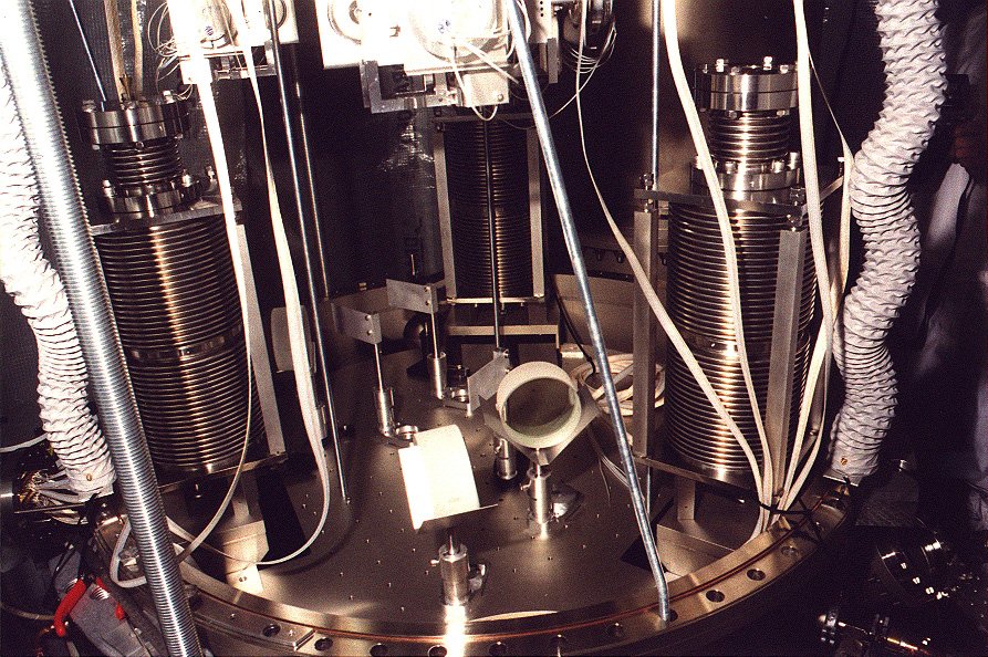
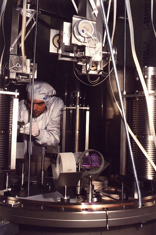
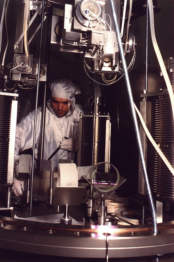
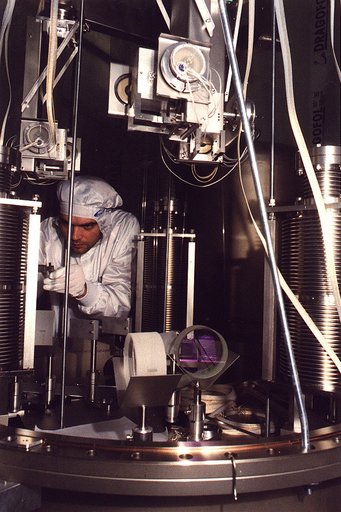
Stefan adjusting the beam director. Above: The local controls for the modecleaner mirrors.
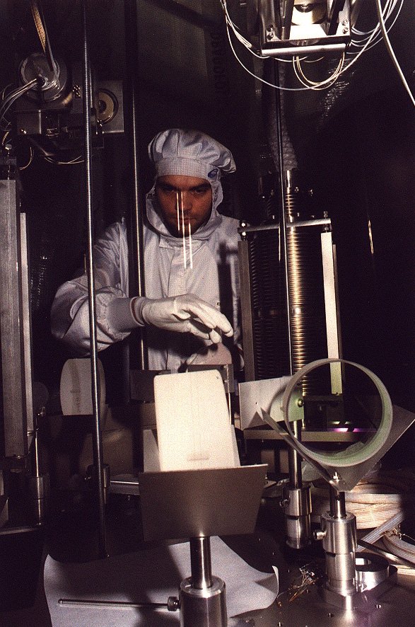
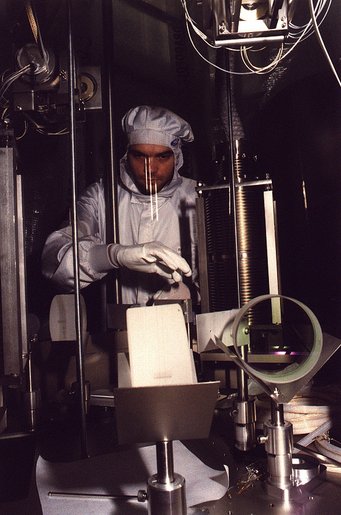
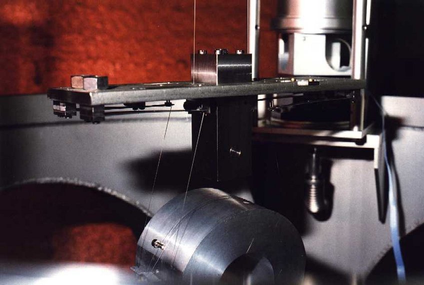
In front of Stefan's face one can see the thin (60 µ) suspension wires reflecting light.
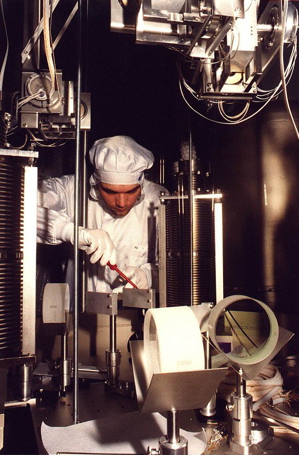
Stefan installing the beam director.
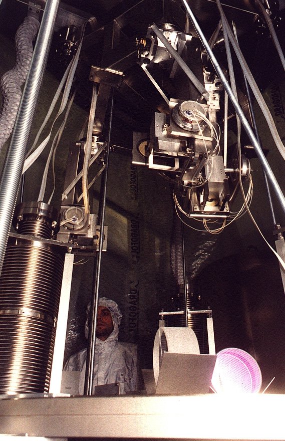
A look upwards to the hovering top plate with suspension and local control units.
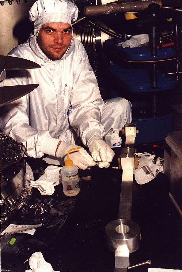
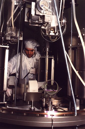
Stefan installing the double pendulums.
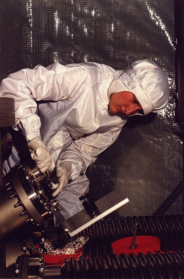
Valerie installing the camera for the mirror monitoring system.
March 1999: Inside Modecleaner Tank TCMa
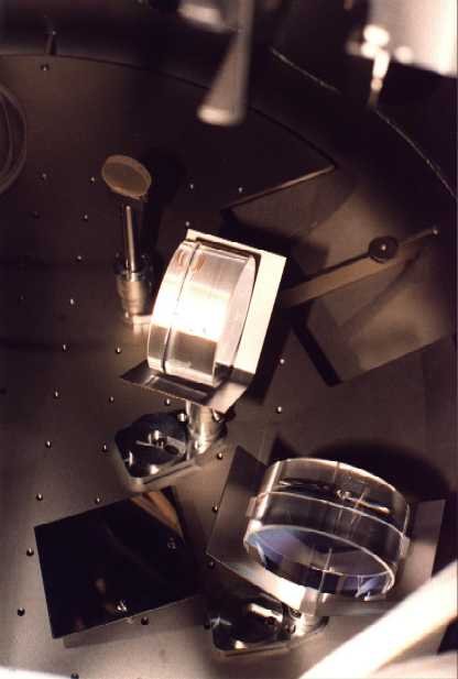
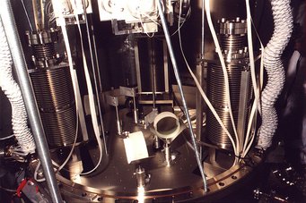
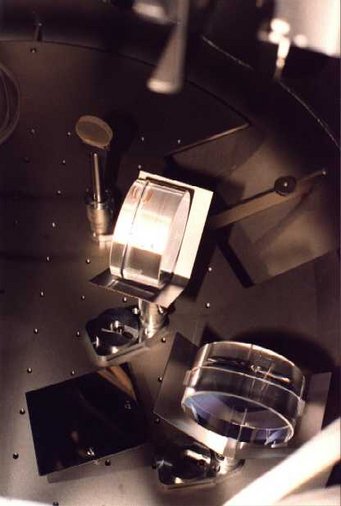
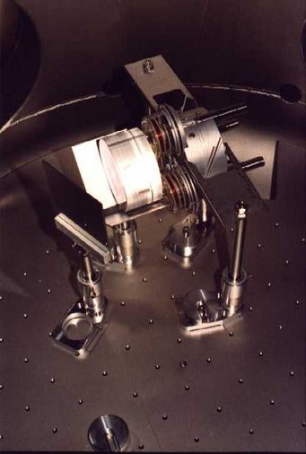
Mirrors MMC1a and MMC1c hovering above their catchers. In the back the small pick-up mirror for the photodiode signal.
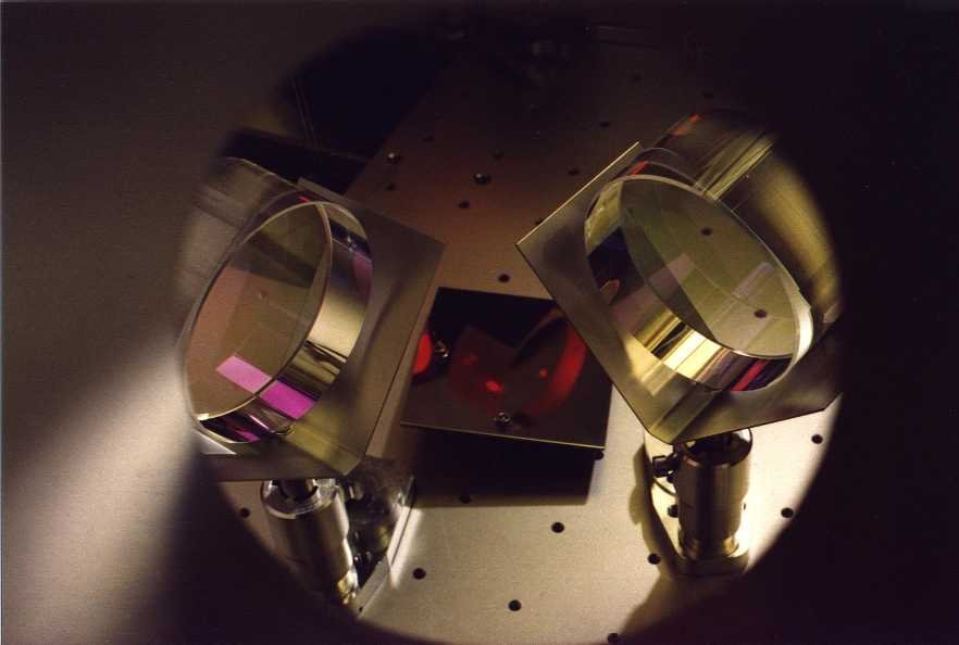
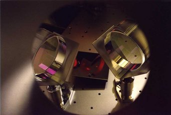
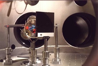
MMC1a and MMC1c seen through the viewport of the camera. The stainless steel plate at the bottom allows to view mirror BDIMC1.
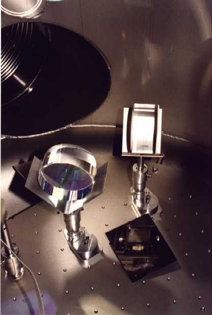
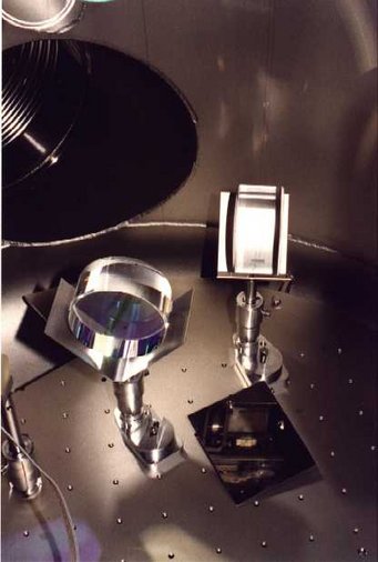
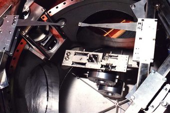
Pick-off mirror, MMC1a, MMC1c, and stainless steel mirror with camera viewport in the back.
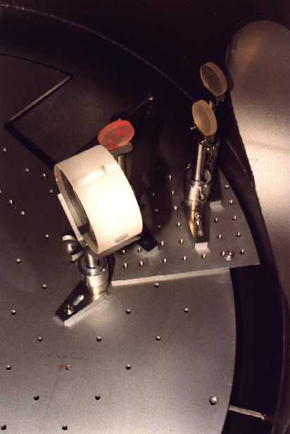
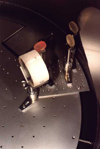
Beam director mirror and pick-up mirror for the transmitted beam; on the right hand side the pick-ups for the beam from MMC1c.
March 1999: Inside Modecleaner Tank TCMb
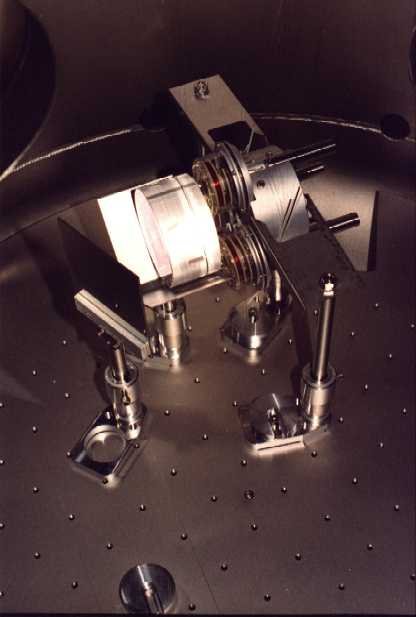
Mirror MMC2b with coils and reaction mass.
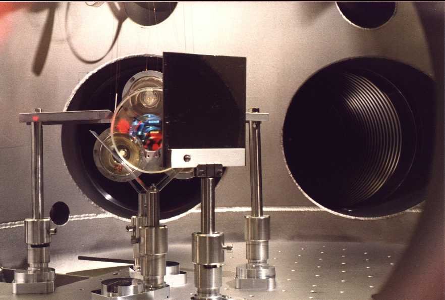
A look through the camera viewport: In front the stainless steel mirror, then mirror MMC2b, behind it the reaction mass with coils; in the back the modecleaner tubes.
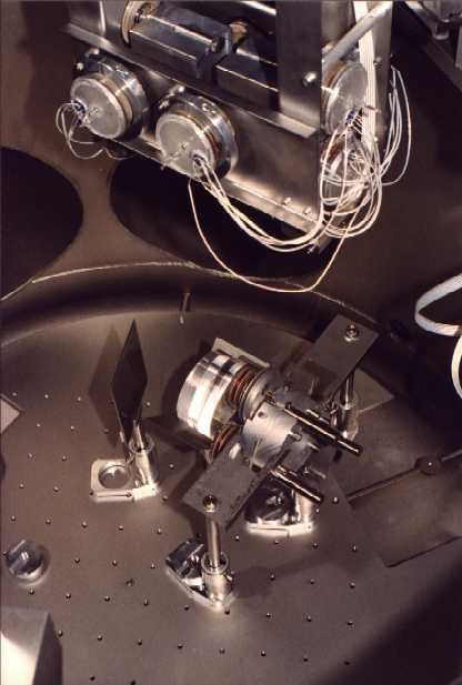
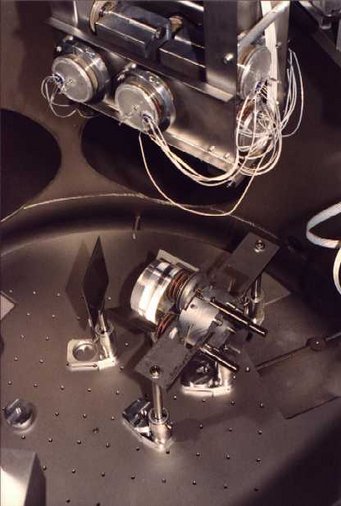
A view from SSE: At the top the intermediate masses with coil holder; at the bottom mirror MMC1b and it's reaction mass between range limiters.
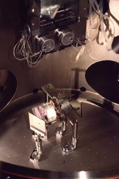
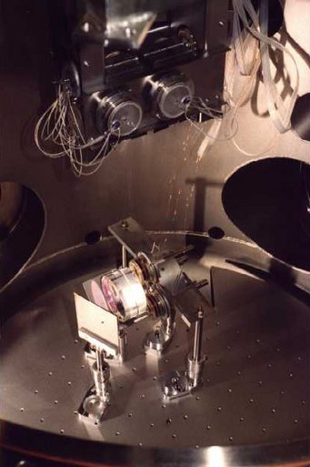
A view from SSW. The thin (50 µm) copper wires are the electricity supply for the coils of the reaction mass.
Impressions from the Site in Spring
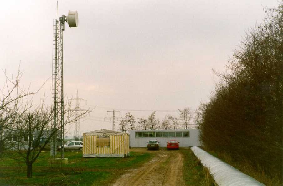
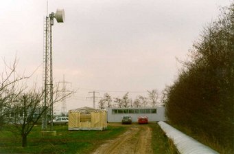
The tent at the feet of the transmitter mast serves as stores. In the back one can see at left the workshop container. The automobiles surrounding the central building indicate the activities at the site.
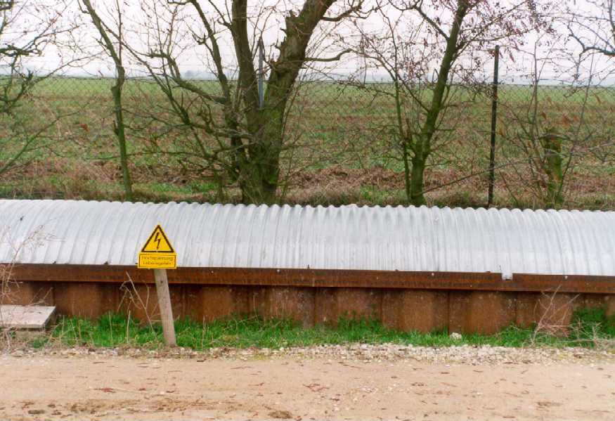
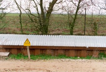
Part of the covered trench with warning. During the period of heating a current of 600 A flows through the tube.
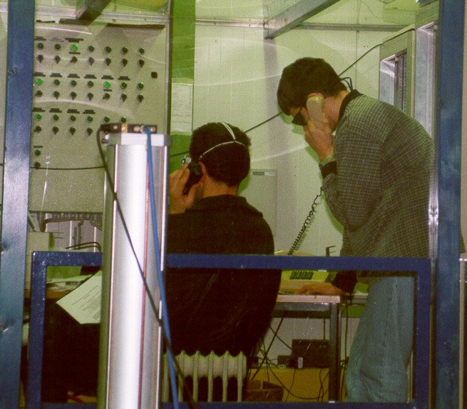
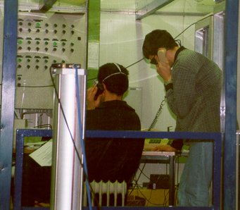
The control room in the central building. Harald and Benno supervise the activities.
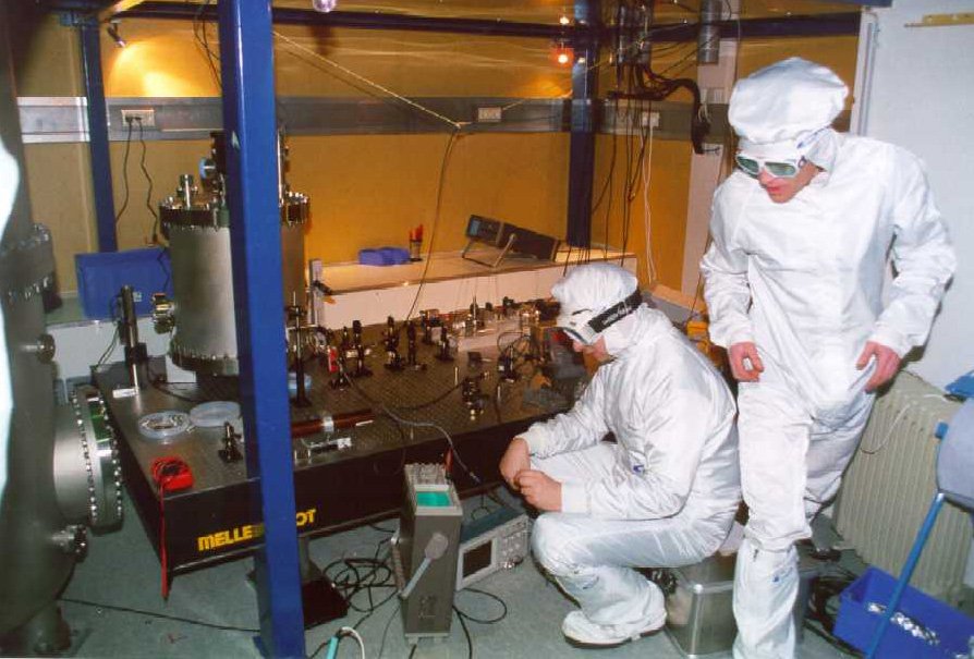
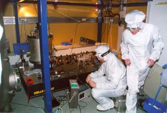
Ken and David control the modulation index of the Pockels cell. The vacuum chamber contains the reference cavity of the frequency stabilization.
May 1999: Breadboard and Scanner
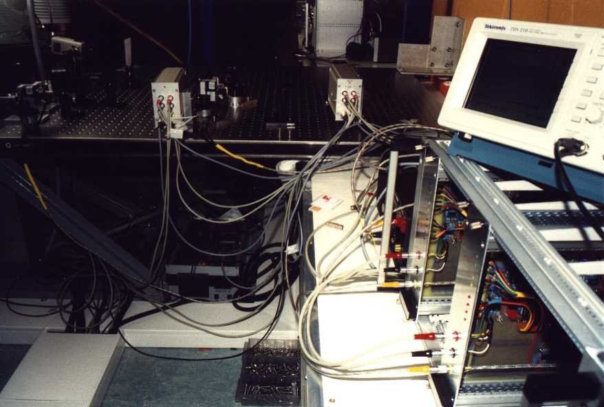
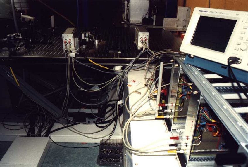
Cameras and electronics for the auto-alignment.
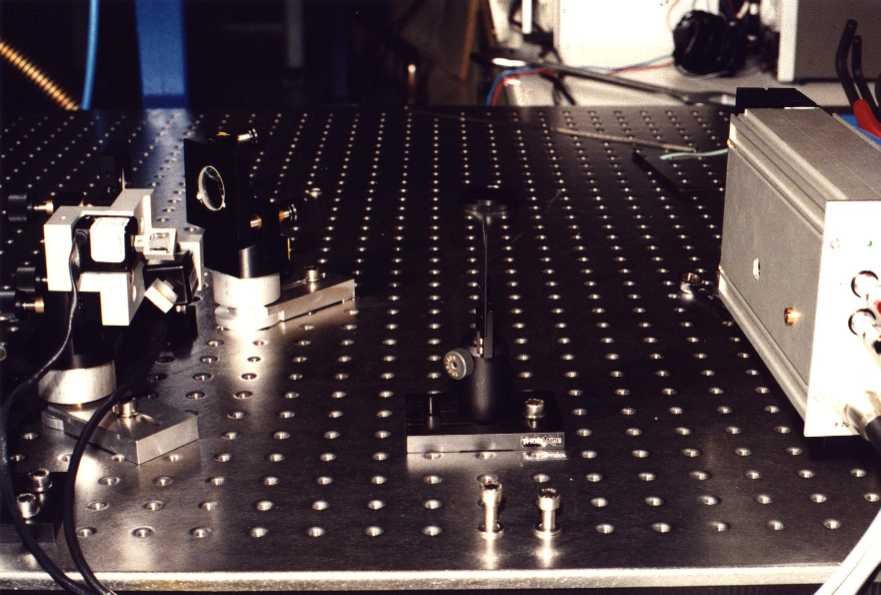
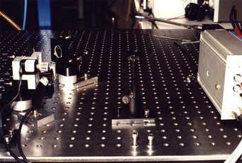
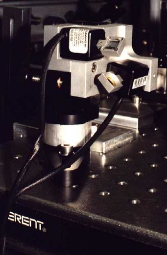
On the left: galvo-scanner, on the right: camera.
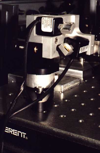
The galvo-scanner fixes the laser beam onto the camera.
June 1999: Test Run of the Main Suspension
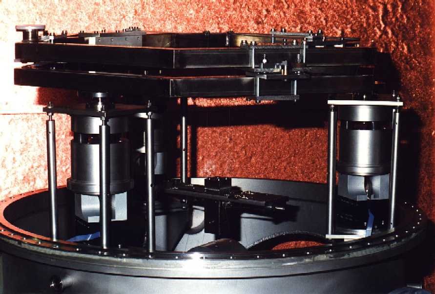
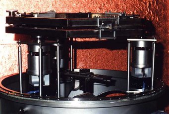
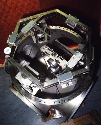
The hexagonal top plate lies on the active/passive seismic isolation stacks; above the top plate the rotational stage.
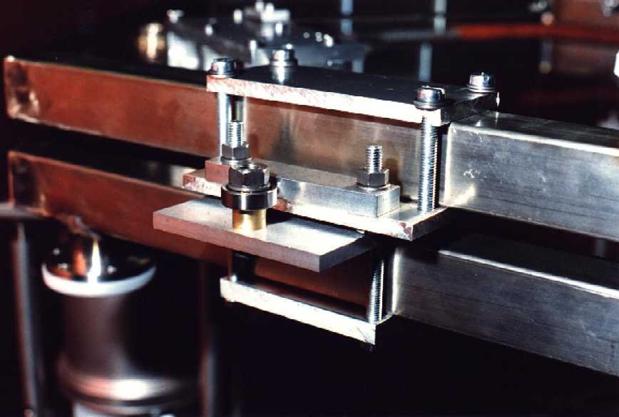
Guidance of the rotational stage.
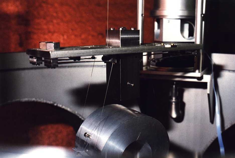
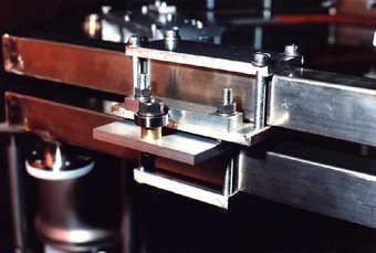
Details of the upper mass: suspension wires and four small cantilever springs for the intermediate mass.
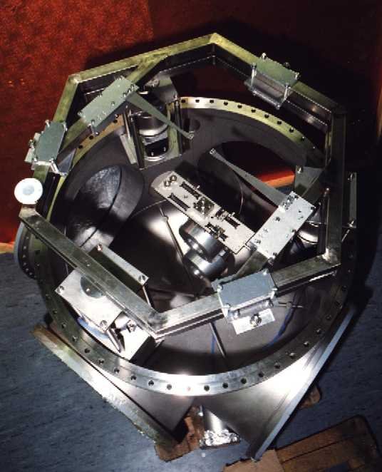
The complete triple pendulum suspension with a mirror dummy.
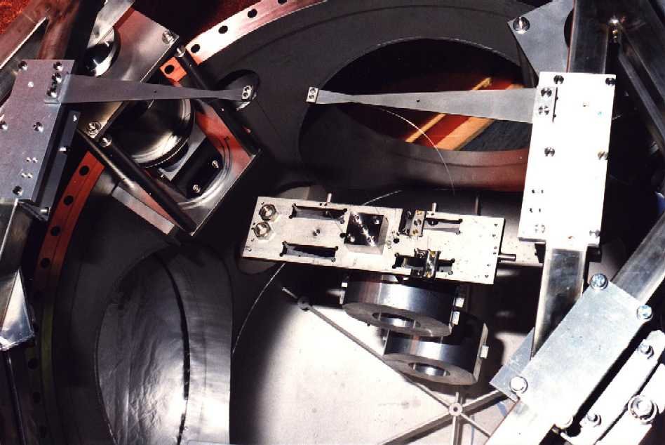
The triple pendulum: cantilever springs, upper mass, intermediate mass and test mass dummy.
Meanwhile at the Site
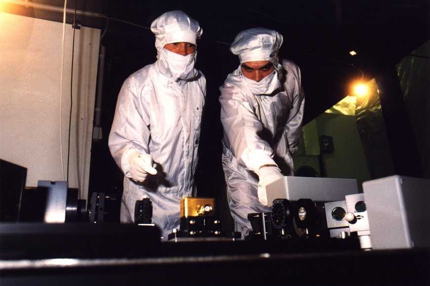
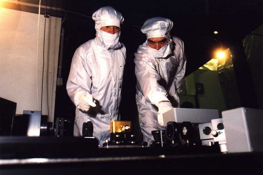
Kerstin and Stefan are controlling the laser system (left hand side).
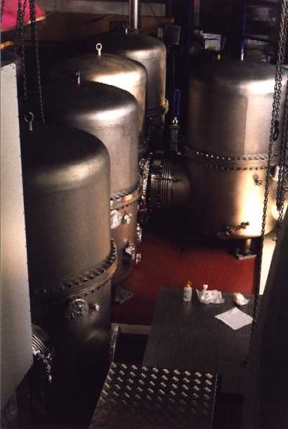
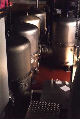
The central cluster of vacuum tanks.
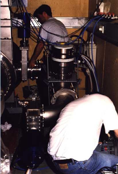
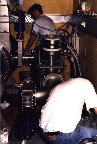
Kasem and Walter are installing a new turbopump.
December 1999: Status Report
Mode-cleaners
Both mode-cleaners (MC) are installed and lock reliable to the light of a prestabilized NPRO (700 mW). Only little time was spent on the mode matching, hence we got only 85% of the light into the first MC. The second MC sees a nicely spatial filtered beam, and the reflected power goes down to 5% once it is locked. The lock bandwidth of MC1 is above 1 kHz; at the moment MC2 is locked with only 400 Hz unity gain.
Main Suspension
The first main triple pendulum suspension system with an Al dummy mirror is installed in TFE. This pendulum is damped by means of a 6-channel local control board with an attached digital board. So it is possible to read the flag position and the feedback signal with a LabView program which can be used to change gains and offsets as well. Mike and the suspension team are in the process of installing the first double-triple pendulum for MCE. It will be pre-assembled outside of TCE and installed early next year.
Power Recycling Tank
All parts are machined and cleaned. The pendulums for MPR and BDIPR will be installed once the TCE pendulums are ready.
Vacuum System
The central cluster (without TCOa and TCOb) is assembled and attached to the mode-cleaner section. The pressure in the central cluster is 3x10⁻⁸ mbar. As the concentration of hydrocarbons is a little high in the mode-cleaner section an aperture was installed at the output of TCMb in order to form a differential pumping system for hydrocarbons between the mode-cleaner section and the main cluster. After the installation of the MFE pendulum we attached the east end tank TFE to the gate valve and pumped it down. The residual gas spectrum looks quite promising.
Control
The first version of the "LabView Control Program Backbone" (for experts: the MCPs, data socket server, and handys) was installed and works fine.
Data Acquisition
Not much happened concerning the DAQ System in Ruthe, but a lot of preparation work has been done. We expect a lot of progress next year. The new radio link (34 Mb/s) will be installed until the end of February. The first data chain check from the site to Hannover and an overnight transfer to Potsdam is planned for March.
Merry Xmas & a Happy New Year!
